

LCD Common Emitter Transistor Amplifier For Lab at 9800 in Ambala Circuit Diagram A 0.05

IOT Weather Station Using ESP32 Wifi Module Arduino Project Circuit Diagram
IOT Weather Station Using ESP32 Wifi Module Arduino Project Circuit Diagram In this article, we'll
How to make a Laser Security Alarm Circuit Diagram
How to make a Laser Security Alarm Circuit Diagram A laser-based security system is a

PCB Layout Services Circuit Diagram
PCB Layout Services Circuit Diagram Step 3: PCB layout stage. The PCB layout stage includes

DIY Supercharged Bluetooth Speaker v20 Circuit Diagram
DIY Supercharged Bluetooth Speaker v20 Circuit Diagram Learn how a Bluetooth speaker works and what

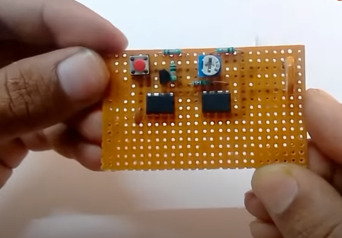
Microcontroller Schematic Diagram Circuit Diagram
Microcontroller Schematic Diagram Circuit Diagram Learn what a microcontroller is, how it works, and how

Voice Recognition Based Home Automation Circuit Diagram
Voice Recognition Based Home Automation Circuit Diagram Home Assistant and Assist is configured following our
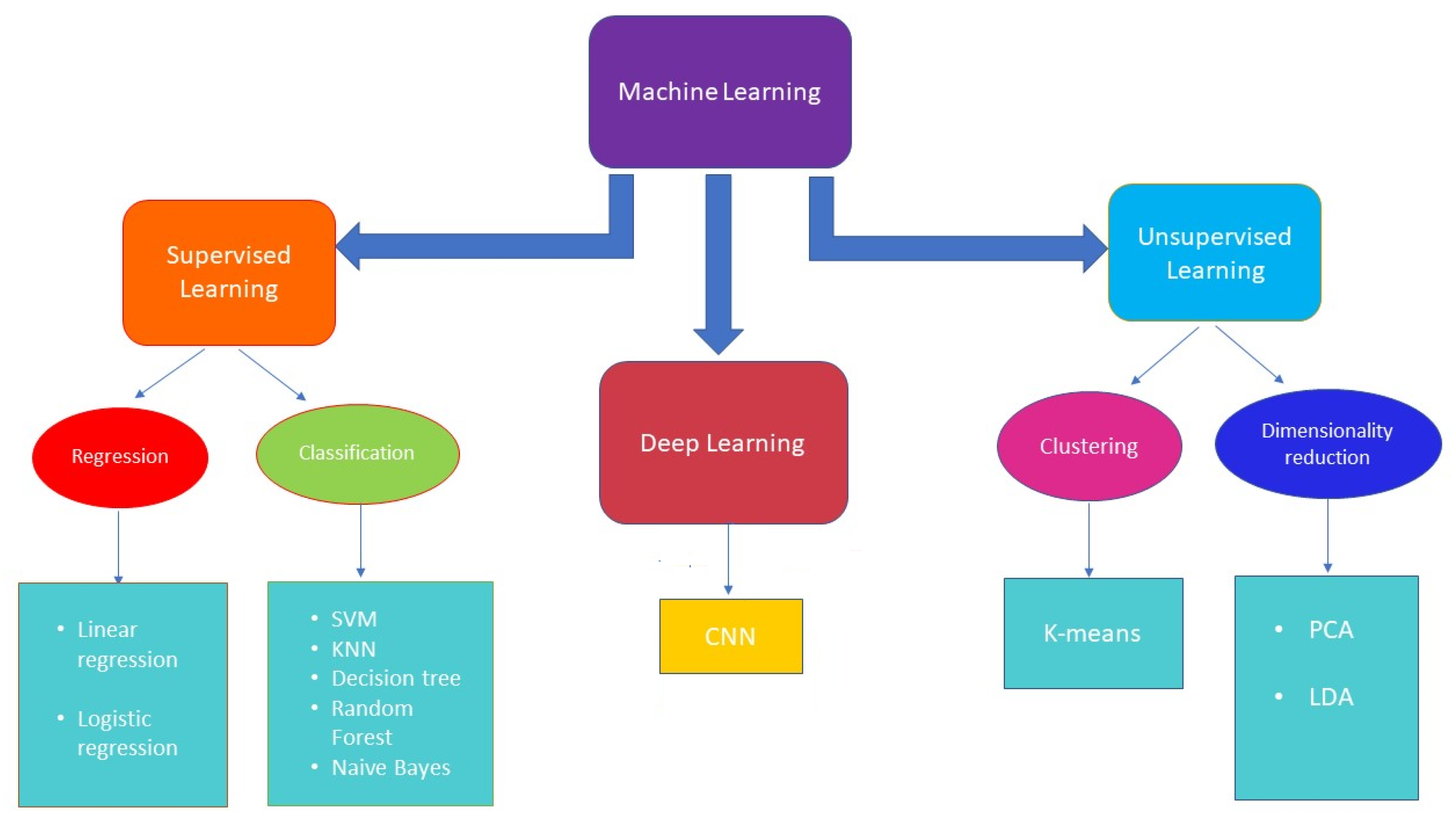
Recent Advances in Machine Learning Circuit Diagram
Recent Advances in Machine Learning Circuit Diagram In the case of the query "machine learning
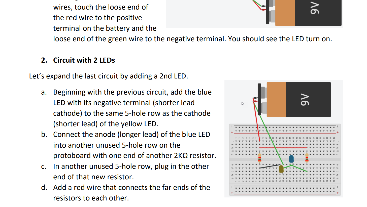
Solved 1 Basic Circuit to turn on 1 LED We will use the Circuit Diagram
Solved 1 Basic Circuit to turn on 1 LED We will use the Circuit Diagram

Future Kit 12V Step Down Regulator DIY Kit Circuit Diagram
Future Kit 12V Step Down Regulator DIY Kit Circuit Diagram The Tail Servo Step-Down Voltage
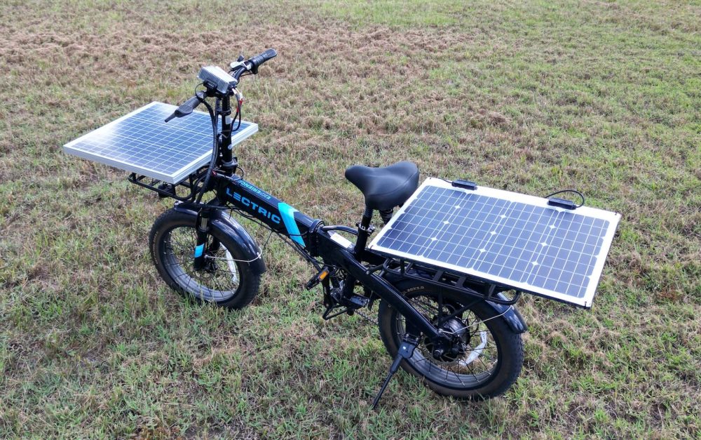
bike for a lifetime of free charging Circuit Diagram
bike for a lifetime of free charging Circuit Diagram DIY solar power projects have always
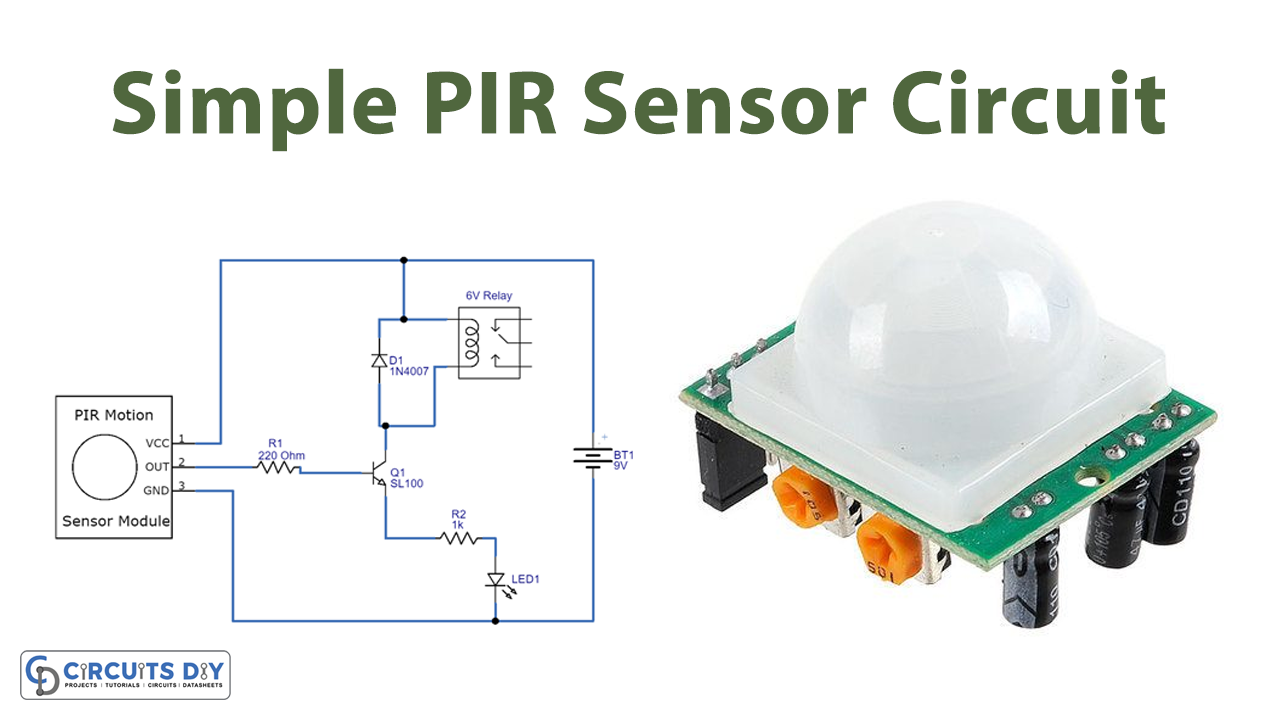
Pir Sensor Circuit Diagram
Pir Sensor Circuit Diagram PIR sensors operate using a simple two-pin logic. When the sensor

citypng by Erwin Max Circuit Diagram
citypng by Erwin Max Circuit Diagram IoT sensors, devices, and systems work together congruently to
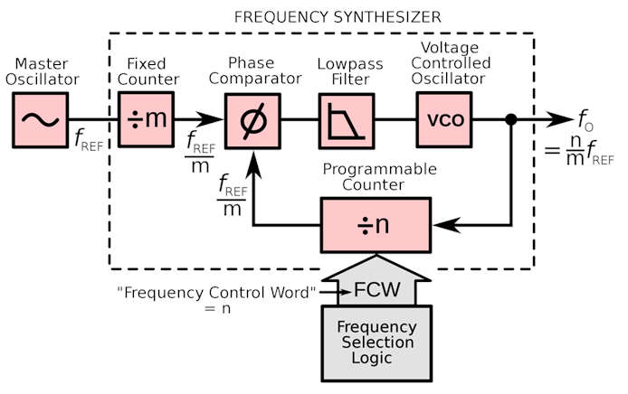
What is an RF Frequency Synthesizer and Applications Circuit Diagram
What is an RF Frequency Synthesizer and Applications Circuit Diagram 2:00 - 3:30 RF front-end

Automatic Temperature Controller DC Fan using Thermistor Circuit Diagram
Automatic Temperature Controller DC Fan using Thermistor Circuit Diagram In this blog, we will guide

Heres How You Can Build Your Own Wind Turbine At Home Circuit Diagram
Heres How You Can Build Your Own Wind Turbine At Home Circuit Diagram Blades: The
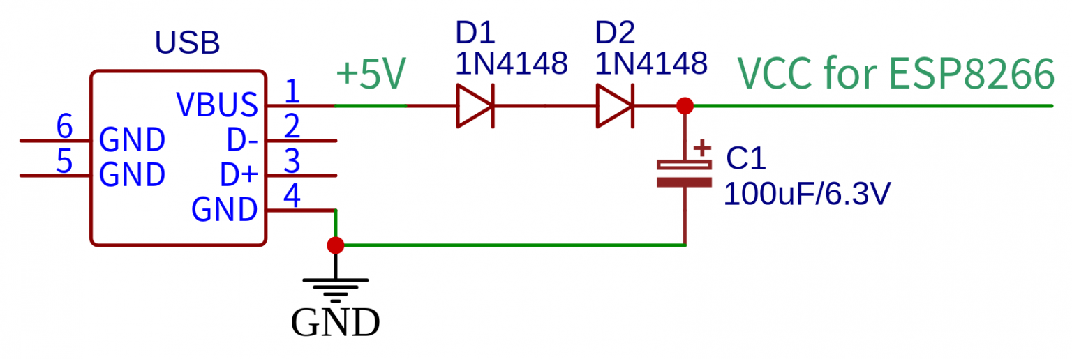
Learning Electronics Tips and Tricks for using ESP8266 in my circuit Circuit Diagram
Learning Electronics Tips and Tricks for using ESP8266 in my circuit Circuit Diagram We have

Figure 1 from Design and Implementation of an IoT Circuit Diagram
Figure 1 from Design and Implementation of an IoT Circuit Diagram This project will enable
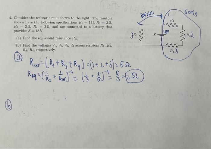
Solved 4 Consider the resistor circuit shown to the rig Circuit Diagram
Solved 4 Consider the resistor circuit shown to the rig Circuit Diagram The next time
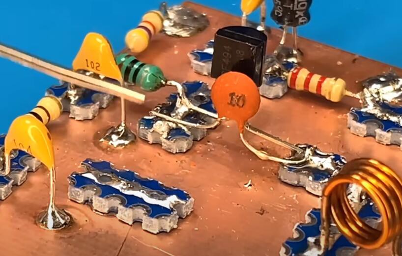
how to make a simple fm radio Circuit Diagram
how to make a simple fm radio Circuit Diagram Need a super simple way to