
GPS Interfacing with Arduino Fritzing Diagram Arduino Projects Circuit Diagram A GPS tracking unit is a device that uses the Global Positioning System( GPS ) to determine the precise location of a vehicle, person, or other asset to which it is attached and to record the position of the asset at regular intervals.The recorded location data can be stored within the tracking unit, or it may be transmitted to a central location data base, or internet-connected computer

Tiny GPS Tracker: This project uses TinyCircuits to create a tiny GPS tracking and data logging device. This tutorial is for any skill level - no coding, programming, or soldering required! Projects Contests Teachers Tiny GPS Tracker. By TinyCircuits in Circuits Arduino. 168,208. 150. 18. Introduction: Tiny GPS Tracker. By TinyCircuits Small GPS Tracker uses component's GPS Neo-6m, Sim800l, Arduino Nano,16×2 LCD Display, Push Button And Buzzer. Check Small Watch GPS Track. We Have Also built many types Of Vehicle Tracking Systems If You are Interested Plz Check Out. WOMEN Safety System; GPS Tracker Using Nodemcu; Arduino GPS and based Location Tracking System
Build Your Own Gps Tracking System Using Arduino Circuit Diagram
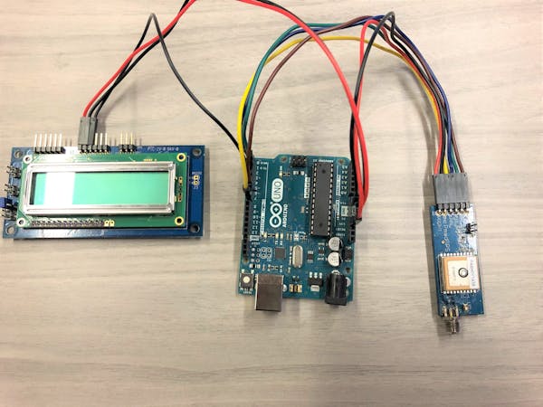
In this article, I create a powerful GPS tracking device using Arduino and the Sim800L GSM module. This simple yet effective project allows you to track the. Circuit Diagram. In this circuit diagram, we connect all the components properly Like the Neo-6M GPS Module connected to the PINs D10 And D11.

Today, we're going to build a smart gps tracker using Arduino that can help you keep tracking location in real time LOGIN. REGISTER. SHOP. ABOUT US. HELP. FAQ. Explore Components on DigiKey Smart GPS Tracker Circuit . Now, connect the components as shown in the diagram below: Connection created in Fritzzing. Arduino based GPS Tracker
Arduino GPS Location Tracker Using NEO6MV2 Circuit Diagram
In this article, I design a simple GPS tracking System using the Arduino Nano, GSM(Sim800l) and GPS(NEO-6m). GPS tracker is essential because you are used in Circuit Diagram. I will design the proper circuit diagram so you do all connections correctly and put the SIM card in the GSM Module. GPS Module Is connected to the PIN D7 And D8. Circuit Diagram for GPS Tracker. As seen from the circuit diagram, we mostly use the digital pins of the Arduino board for the operation, except for one analog pin that is connected to the
