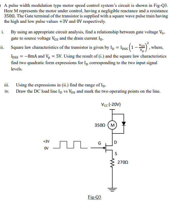
PulseWidth Modulation DC Motor Control and Servo Circuit Diagram Pulse Width Modulation (PWM) is a powerful and widely-used technique in modern electrical engineering, particularly for controlling the speed of DC motors and optimizing power conversion. By adjusting the width of the pulses in a signal, PWM allows for efficient control of motor performance, delivering precise regulation of motor speed and torque. A pulse-width modulation signal begins with a voltage that goes up and down repeatedly. The classic method of creating the oscillation is with a resistor-capacitor (RC) circuit. This circuit uses RC timing with a diode twist to alter the ratio of the on-pulse time versus the off-pulse time (called "duty cycle"). PWM, short for Pulse Width Modulation, is an important concept in modern electronics. It is generally used as a power delivery mechanism in motor control and lighting control systems. You can easily modify the above circuit to control the speed of a DC Motor. Related Posts: Low Power Audio Amplifier using 555 Timer; PWM LED Dimmer Using
The objective of this design project is to develop and prototype a high efficiency pulse width modulation (PWM) speed control for a small DC motor. A block diagram of the overall system is shown below: Figure 1. Block diagram of the PWM DC motor speed control Background:

PDF Laboratory Design Project: PWM DC Motor Speed Control Circuit Diagram
Projects using these devices need a varying voltage to control the position, brightness, or speed of the device. But most microcontrollers are unable to generate this varying analog voltage. Pulse width modulation is used to simulate this varying analog voltage using a digital microcontroller or timer. How Pulse Width Modulation Works

In this article, we will take a look at how you can easily design a PWM DC Motor Controller with a NE555 timer IC using EasyEDA & JLCPCB services & a small number of other components. The TL494 is a fixed frequency, pulse width modulation control circuit designed primarily for switchmode power supply control. TL494 Pinout TL494 Pin
Pulse Width Modulation Used for Motor Control Circuit Diagram
Also the amplitude of the motor voltage remains constant so the motor is always at full strength. The result is that the motor can be rotated much more slowly without it stalling. So how can we produce a pulse width modulation signal to control the motor. Easy, use an Astable 555 Oscillator circuit as shown below.