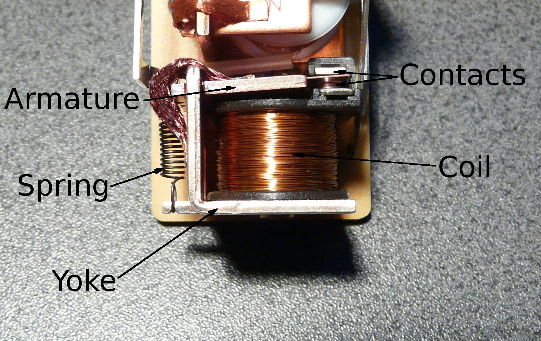
voltage AC generation using relays R X Seger Medium Circuit Diagram Relays range from electromagnetic and reed relays to solid-state, hybrid, and thermal relays. A standard AC or DC electromagnetic relay consists of an electromagnet that receives an electric signal and converts the signal into the mechanical action of a switch that opens and closes the circuit. A reed relay features a pair of magnetic strips Reed Relay: Reed relays use a reed switch enclosed in a coil to control the switching action. They are compact and suitable for high-speed switching applications. Polarized Relay: Polarized relays have contacts that are polarized to ensure proper operation in DC circuits. They are designed to prevent reverse polarity issues. However a relay switch circuit can be used to control motors, heaters, lamps or AC circuits which themselves can draw a lot more electrical voltage, current and therefore power. The electro-mechanical relay is an output device (actuator) which come in a whole host of shapes, sizes and designs, and have many uses and applications in electronic
We can use a Relay either in a AC circuit or a DC Circuit. In case of AC relays, for every current zero position, the relay coil gets demagnetized and hence there would be a chance of continues breaking of the circuit. Above image shows working of the relay. A switch is used to apply DC current to the load. In the relay, Copper coil and the Lets take a simple example where we will be turning on an AC lamp by using a relay switch. In this relay circuit we use a push button to trigger a 5V relay, which in turn, complete the second circuit and turn on the lamp. (CFL) by using a relay switch. In this relay circuit we use a push button to trigger a 5V relay, which in turn, complete
How a Relay Works and How to Use It in Circuits Circuit Diagram
Let's switch a lamp on and off using a relay in a circuit. We'll use both non-latching and latching relays. Relays are useful for using small signals to sw Instead, we can use a large relay (at this scale, they are generally referred to as contactors) to do the switching and control the relay from far away using a much lower voltage. This setup allows us to turn on the motor using a switch in just a 24 V circuit, which is physically far away from the high-power one. At the heart of this circuit is a 5V relay, which acts as an intermediary to switch the high-power AC load while being controlled by a low-power DC signal.Here's a breakdown of the components and their roles: Battery (9V): Supplies power to the control circuit. Switch (SW1): Turns the entire circuit ON or OFF. NPN Transistor: Amplifies the control signal to drive the relay.