Writing to Shift Registers on a LED Display Board AskElectronics Circuit Diagram 🚀 In this tutorial, we'll learn how to use the 74HC595 shift register with an Arduino Nano to control 10 LEDs with different lighting modes. This method hel

Code to Control LEDs using the 74HC595 Shift Register. Firstly, it allows you to control multiple outputs using only a few Arduino pins, which is especially useful when you have limited pins available. Secondly, it reduces the amount of wiring required, making your project more organized and easier to manage. Connecting the shift register; Connecting the LEDs; Connecting your Omega; It's going to be similar to the second experiment, but this time we're going to use 8 LEDs and a shift register. Refer to the circuit building instructions in Experiment 2, except you will be connecting 8 LEDs to the shift register instead of the Omega's GPIOs.

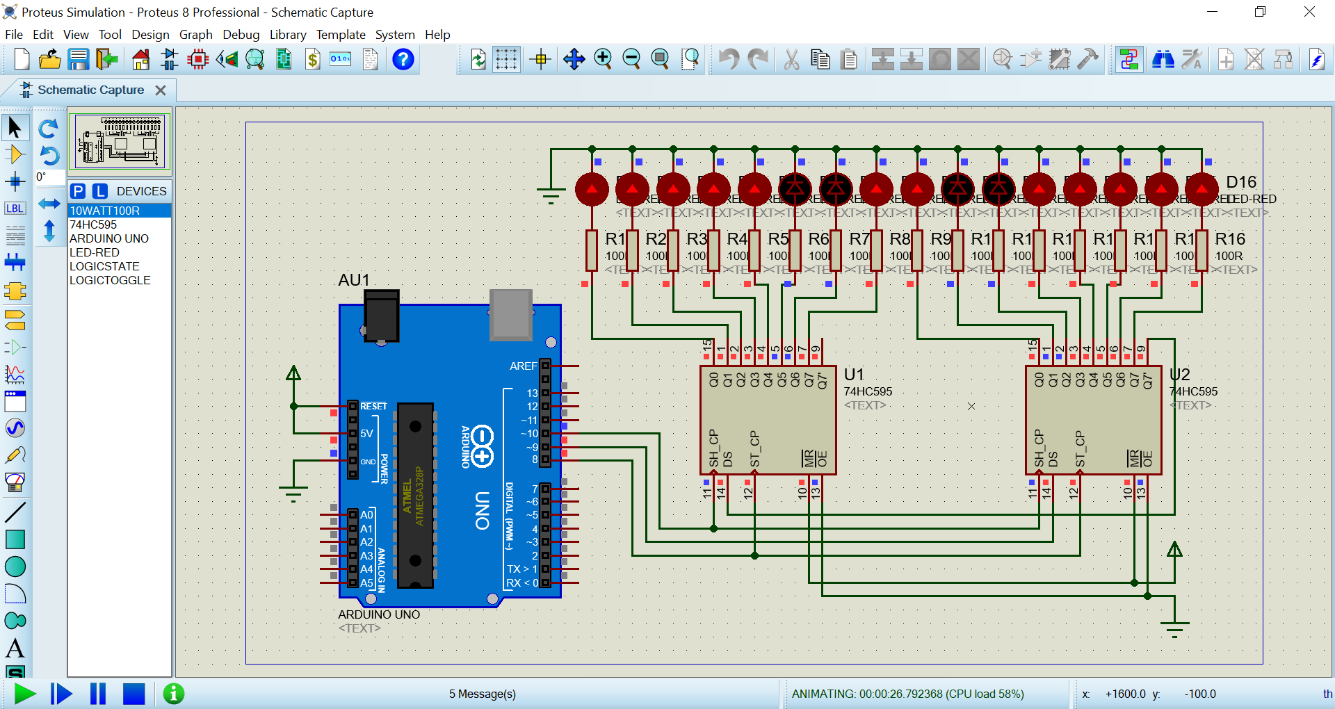
Arduino 16 LEDs Using Two 74HC595 Shift Registers (unlimited Pins) Circuit Diagram
In order to save on pins I am using a shift register to control the columns. This way I can control an almost unlimited number of columns with just four microcontroller pins. It is possible to use only three if the Enable Output pin is tied directly to voltage. I have selected the HEF4794 LED driver with shift register.
5.1 Using the 74HC595 Shift Register . In this lesson, we'll learn how to use the 74HC595 shift register to control multiple LEDs with just a few GPIO pins on the Raspberry Pi Pico 2. The 74HC595 is an integrated circuit (IC) that allows you to expand the number of digital outputs using a serial input.
LED Matrix Using Shift Registers : 7 Steps (with Pictures ... Circuit Diagram
This demonstrates how the 74HC595 shift register can be used to control multiple outputs with only three control pins from the microcontroller. Conclusion This experiment shows how the 74HC595 shift register can be used to expand the output capabilities of a microcontroller, allowing it to control 8 LEDs with only 3 digital pins. By using a shift register, the LED chaser can control multiple LEDs with fewer output pins from the microcontroller. For example, a single shift register can control up to 8 LEDs with only 3 output pins from the microcontroller. while a microcontroller without a shift register may need 8 output pins to control the same number of LEDs.